


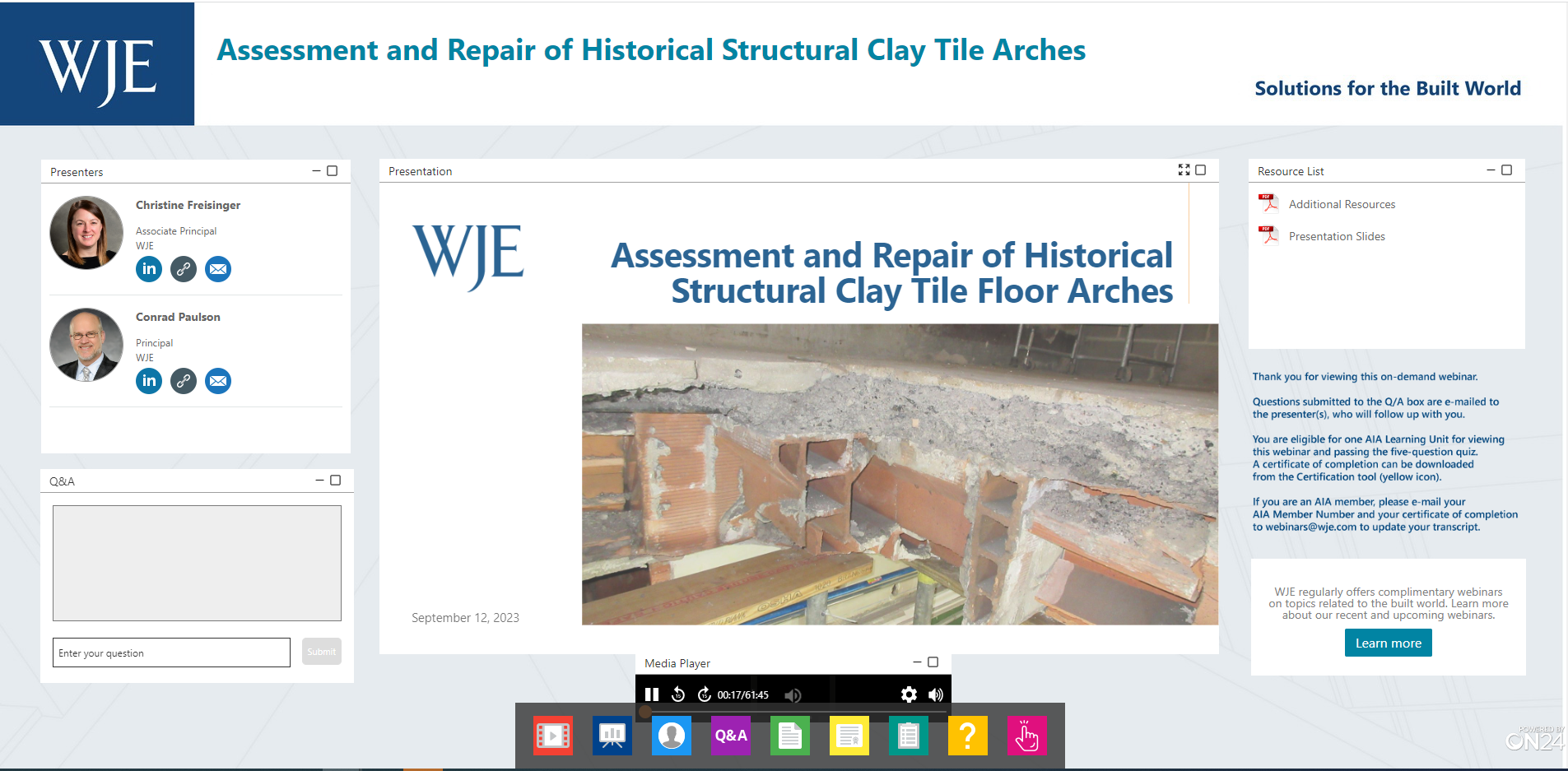
Structural clay tile floor arches were commonly used in late 1800s and early 1900s building construction to create a fire-resistive floor system. Although flat in appearance, the system behaves like an arch, spanning between steel floor beams to support its own weight as well as the superimposed dead and live loads on the floor. When properly maintained, historical clay tile floor arches can continue to provide adequate strength; however, clay tile is an extremely brittle material that tends to fracture when exposed to vibratory conditions, such as hammer drilling. Damage to clay tile is cumulative, and successive buildouts or renovations will cause additive damage to a clay tile floor arch system.
In this webinar, WJE structural engineers Christine Freisinger and Conrad Paulson summarize the history of clay tile floor arches, explain their structural behavior, and provide guidance for repairing typical damage as well as for removing portions of a floor arch system during renovation projects.
By the end of the webinar, you will be able to:
• Describe the structural behavior of clay tile floor arches
• Explain the advantages and disadvantages of historical clay tile floor arches
• Identify cumulative damage to clay tile floor arches due to successive buildouts
• Summarize the methodology for repairing a damaged clay tile floor arch
more to learn
View this webinar in our interactive audience console to earn 1 AIA HSW learning unit, access related resources, submit questions to the presenters, and download a certificate of completion.
Conrad Paulson, Principal
LIZ PIMPER
Welcome to today's WJE Webinar, Assessment and Repair of Historical Structural Clay Tile Arches. My name is Liz Pimper and I'll be your moderator. During the next hour, structural engineers, Christine Freisinger and Conrad Paulson will summarize the history of clay tile floor arches, explain their structural behavior, and provide guidance for repairing typical damage as well as for removing portions of a floor arch system during renovation projects. This presentation is copyrighted by Wiss, Janney, Elstner Associates. And now I will turn it over to Christine to get us started. Christine?
CHRISTINE FREISINGER
Thanks, Liz. Thanks, everyone for joining Conrad and I today. We'll be diving into the topic of historical structural clay tile floor arches. We've had the pleasure of working on many of these systems within vintage buildings around the country. Some of the principles presented here also apply to unreinforced masonry arches such as [inaudible 00:00:53] arches, which are also a very interesting topic.
At the end of the presentation today, you'll know a lot more about structural clay, tile floor arches, why they were used, how they were designed, and how they can be repaired. To get us through the learning objectives, we'll be following this outline with Conrad and I tag teaming the list. At the end, we'll give you a few key takeaways to remember when you're working on these systems.
So let's get into the introduction. When we hear historical structural clay tile floor arches, what are we talking about? So we're describing the type of floor system that was popular from the 1870s to the 1930s. And the system consisted of terracotta blocks that are laid together to form an arch and then that arch is supported by steel framing. Clay tile blocks were also widely used for fireproofing and partition walls.
Clay tile systems are not photogenic. So throughout the presentation, Conrad and I will be using yellow labels to call up portions of the system that are visible in the photo. Conrad will be discussing the systems in depth in the next section. So for now, I just want to leave you with an overview of what a clay tile system looks like in the wild.
If an opening is created in the floor system such as the photo on the left, you're able to see the original wood flooring and non-structural cinder fill on top of the cross-section of the clay tile arch. That arch is then supported on the steel beams. Most often the underside of these systems have an adhered plaster ceiling, but in some instances, the plaster ceiling has been removed, which is shown in the photo on the right, and the underside of the individual clay tile blocks is visible.
Clay tile systems are very strong but unfortunately are not very redundant, so we often refer to the children's game of don't break the ice to describe these systems. Removing or damaging too many individual blocks can cause a collapse of the arch. You want to keep in mind that these systems behave different from our modern floor systems such as reinforced concrete slabs or concrete top metal ducts.
Here's a view of the system from the top side, which would be the walking surface. Up in the upper right-hand corner, you can see the remains of the original wood flooring system and the non-structural cinder fill that have remained. And in the area where that topping has been removed, you can see the top surface of the clay tile blocks and you can also see the exposed steel beam. The occasional holes that you see in these tile blocks are considered small and do not affect the strength of the arch. Again, we're thinking of don't break the ice in these situations.
Here's another photo showing another opening an arch system. So you can see in the background the cross-section of the arch, and you can see the supporting steel beams that are also passing through the opening. Several advantages for the clay tile system made this very popular, as I mentioned, around 1870s to 1930s. The simple flat false work permitted rapid construction, so a dance floor was constructed and the workers could stand on that to lay the individual blocks. Lower skilled labor could be used for this construction and the arch was set and could take load as soon as all the blocks were in place. There was no need to wait for mortar to set.
Additionally, the system provides a flat ceiling and removes the need for a suspended ceiling overhead. The plaster, as I mentioned before, is often adhered directly to the blocks. The 1870s fires in Chicago and Boston highlighted to the building industry that brick is one of the better fire-resistant materials available. Designers and cities started using it or requiring it more and more in high-quality buildings to provide that fire resistance that everyone was looking for in high-rises.
Due to this increased use, more testing and engineering was being completed on the clay tile blocks themselves in the system overall to improve material properties and create more efficient structural systems. The images on the right are examples of the improved clay tile cross sections to use less material and provide longer arch spans. This made it more attractive to engineers that were looking to save materials during construction.
The clay tile blocks themselves are made of terra cotta, which is an extruded mixture of clay and water that ends up being fired. The extrusion process was well known by the time clay tile floor systems started becoming popular. The image on the right shows a terra cotta mold for an ornamental facade element but would've been similar to the floor block molds. The image on the left shows the extrusion process for a current system.
The clay and water mixture is extruded and then air dried and then fired. The resulting blocks are very strong in compression, but also very brittle, so you could easily take a hammer and crack the tiles after a whack or two. Conrad will be talking more about the behavior of the arch to take advantage of the compressive strength and avoid the brittle weakness.
Due to the vintage of buildings that use these systems, the original drawings were often created by hand and have typically been photocopied multiple times by the time we're able to see them. So often we're counting our lucky stars when we come across a legible set of original drawings. When we're looking at the structural sheets, there may or may not be specific information on the clay tiles such as the depth. We often look for visual cues on the drawings indicating the tie rods. Often the structural or architectural sections may also show the clay tile system.
So looking closer at this typical bay that we've got highlighted in magenta and then the blowup on the right, we have the columns highlighted in yellow, the girders are highlighted in orange, the beams are highlighted in green and then the tie rods are showed with the dash lines. The tie rods are typically at third or quarter points of the steel beams. And sometimes seeing those dash lines on plans is really the main indicator that you're working with a clay tile system.
So as I mentioned, the clay tile floor systems are really great in strength and provide really good floor systems due to the compressive nature on the blocks. However, these clay tile blocks are brittle. So what happens when we see damage blocks looking up here at the underside of the clay tile arch? We definitely want to know more about the behavior of the arch to assess what we're seeing and determine the extent of damage that may or may not need to be repaired. We also see images like this looking up at the underside of the clay tile arch.
So Conrad's going to discuss the behavior of the arches and then we'll come back to these case studies to discuss how we assess them and how we determined if repairs were required and then how we completed those repairs. With that, I will hand it off to Conrad.
CONRAD PAULSON
Thank you, Christine, and I would like to thank everybody for taking time out of their day and joining us. As Christine mentioned, we'll be happy to answer questions at the end of the presentation. In an office building, the floor slabs or these arches are flat and they don't have an arching shape to them, but nonetheless, they do function as a real arch. And because of that, we'll do a quick review of arch terminology.
Here we have a simple circular ring arch. It's a fragment or a segment of a circle shape here. And terms that you may hear today is first of all the crown, that is the top of the arch, and then there are hunches. That's the part of the arch to the right and the left of the crown and above the rest of the structure that supports the arch. What does support the arch is called the abutment here. And then above the haunches like the filler material in this wall for this arch, it's called the spandrel area. The spandrel puts load onto the haunch area of the arch.
In terms of the pieces of the arch itself, the blocks or the stones in the arch ring here, the top and center piece is called the key. Down at the support point, these little triangular-shape blocks are called the skew. And that dashed line connecting points C and C, spanning left to right here is called the spring line. You'll hear people talk about the springing of the arch. Well, that's the bottommost point of support. It's where the arch starts to climb vertically from the abutment.
There's a few key dimensions we'll talk about today. The span, first of all, that's the left-right dimension labeled A here in this illustration. The arch has a rise to it and that's the dimension B shown here. The rise extends from the spring line, up to the underside of the keystone. And then the blocks or the stones of the arch ring itself have a depth to them, h, and that is essentially the thickness of the arch ring.
So what happens if we put a load on this arch? The load has to go somewhere and the first thing that happens is the load travels down to the skews and exits into the abutment in the form of these reaction forces shown here. Connecting the load in the reaction forces is something called the thrust line. It travels through the arch ring itself and it's a series of compression forces that form the function of taking the applied load, traveling it through the arch ring, and putting it out into the abutments.
The idea with an arch is the position of the thrust line has to stay within the depth of the arch ring itself. If it travels outside of the arch ring, you're starting to have potential for performance problems with the arch itself. Notice that we aren't talking about tension at all. None of these forces seen here are acting in tension. They're all in compression. Therefore, we have no reason to have tension reinforcement in an arch.
However, some arches do require a tension rod to help with the stability. And what they are actually doing is helping the abutments do their job of resisting the thrust from the arch itself. Here are some illustrations of possible failure modes in an arch. In the upper left-hand corner lettered A, we've applied too much load to the crown of the arch and the crown is settling down. When arches start to fail, the joints between the blocks or the stones and the ring of the arch start to open up as seen in these illustrations.
Illustration B, the upper-right, the haunches of the arch are overloaded relative to the crown. We're starting to pinch the arch and the crown is rising upwards. Illustration C is when the abutments aren't strong enough to resist the thrust, they start to spread apart. That's the purpose of the tie rod talked about in the previous slide. It helps stabilize the abutments to keep them from spreading apart.
And then a fourth failure mode not illustrated on this slide is crushing of the stones or blocks themselves. That's when the material used to build the elements of the arch itself are not strong enough to resist the compression forces of the thrust line passing through the stones or the blocks and they start to crush and break apart.
Arches do fail. This illustration here is from a historical arch that was used in a bridge to carry an aqueduct over a river. The aqueduct was a shipping canal constructed in the 1830s in the eastern part of the United States, and it started to fail in the 1970s. The photo in the upper-right shows the arch before it completely collapsed. You'll notice in that photo a couple of things. The arrows are indicating features of movement and where "hinges" have formed in the central arch of the three spans shown here.
And the interesting thing is the abutment or the pier in the left of center there, it has started to tilt or move sideways to the left in this photo. What's happening here is a couple of things are going on. It turns out that the foundations or the part of the pier that's in the water, the left-hand pier, it suffered erosion over the decades and decades that this arch was in service.
The other thing is if you'll notice, the central span of the arch is longer than the end span to the left and right, and it's also a different configuration. The end arches to the left and to the right are half-circle rings, whereas the arch in the middle is more of an elliptical shape and it is a much longer span. That means the thrust forces in that middle arch are going to be significantly larger than the thrusts force to the left or to the right. And where they meet on that pier between the central arch and the left arch or the right arch, those thrusts forces are unbalance, and it's the unbalance of that thrusts force that is contributing to the tilt scene here.
In the lower left-hand photo, what eventually happened again in the 1970s is the river flooded and the force of the floodwater finished the job of collapsing this arch bridge. This was a significant historical landmark and it was reconstructed in about 2010, 2011 with more modern materials, but an aesthetic that replicated the historical arch.
So there are several types of arch floor systems you may encounter in a building, whether it's office building or warehouse, or factory, and they each had their specialty applications. We'll talk about a segmental brick arch, a segmental tile arch, and a flat tile arch. The segmental brick arch was the first on the scene. It's the oldest of our arch systems that you'll encounter out there. And it's simply made by bricks laid up in the fashion illustrated here springing between these eye beams in the floor slab.
Notice there's a tie rod there. That tie rod is serving the function of stabilizing the lateral movement of the I-beams. The I-beams here are serving as the abutments for this brick floor arch. And the I-beams do serve as abutments for all of the floor arches that we're talking about today. These brick arches were considered "expensive" because they used a lot of material, but they're very strong and thus were well-suited for heavy loads. In fact, if you wanted to get a very, very heavy load through a brick arch, you could always add a second course of bricks and have a two-course brick arch for example.
Other components we see here is the cinder fill above the arch and the finished floor. And we'll talk about those a little bit more in the next slide. The tie rod is shown here by the way, essentially passes along the spring line. That's the most structurally efficient location for the tie rod.
Here we have a segmental tile floor arch. It looks a lot like a brick arch except hollow tiles have been substituted or used in place of the bricks, and there are some specialty tiles that fit around the I-beams that support this arch called the skew and the shoe tile. And those you will encounter in various constructions, also sometimes with flat arches.
Now the segmental arch shown here is considered more economical for the strength provided. There's not as much wasted material with the hollow clay tile. However, when these first came on the scene, these kinds of segmental arches were mostly limited to warehouses or to again heavy load applications and that was because of the aesthetics. Office buildings wanted a flat ceiling and with a segmental arch, whether it's a brick or tile, you'd have to put in a suspended plaster ceiling to get the aesthetics you wanted for an office building. These segmental tile arches do need the tie rod. They're not illustrated here, but they do need them.
This illustration gives you a better idea of the overburden that is intentionally put on top of the arch. Working from the arch ring upward, first, we have what's called a concrete fill. Most often that will be a cinder concrete, which is very weak but lightweight. The strength doesn't much matter because it's just a non-structural filler material. You'll set some wood strips called sleepers into the cinder concrete and then on top of those sleepers, you'll nail down your finished floor system.
And here's a view of one of these segmental clay tile arches from below looking up. You can see the different features, the shoe tiles that are fireproofing for the beams. You can see the individual tiles of the arch ring itself. They are set in what we would nickname running bond, meaning the head joints are staggered and do not align. Except in certain locations you may encounter head joints in alignment and that actually indicates the position of the tie rod. And that's because when these floor systems are built, of course first you put in your column and then your girders and then your floor beams. Then you set the tie rods between the floor beams and at the end, you finally put in all of the clay tile. And so the construction sequence is dictating the presence of that aligned head joints that suggest where the tie rod is.
Here's a photo that is a little bit familiar to you by now. It's our classic office building clay tile flat floor arch. As Christine mentioned, in this photo, we can see not only the tile arch itself but the wood flooring on top of it. There are many advantages as noted. They were very popular between the 1870s and the 1930s. They could be set with inexpensive labor. The false work called centering that you erected these on, could actually be suspended from the steel floor beams and so you didn't need separate scaffolding for that. And then as soon as you set the keystone, so you'll come in, put in the skew backs, put in the other blocks, and set the keystone, the arch is immediately functional. And so, it gets its full strength almost right away.
Now we're calling these floor arches, but you'll occasionally encounter a flat arch in a roof deck. And we'll mention possible roof systems a little bit more later on.
Here's the application of arch terminology to our flat floor arch. Working from the support, the floor beams left and right in this photo, those are analogous to the abutments. And then working in towards the center of the arch, first you have the skew backs, then what are called intermediate or lengthener blocks, and then the key block in the middle. Sitting on top of this flat arch is the non-structural cinder concrete fill and then the wood flooring system on top of that.
Just a quick little side note. The terminology for the arch components used here is what's commonly used historically with flat arches. But arches in general have numerous synonyms for these different terms. You may find if you go into a classical architectural handbook or a structural engineering book talking about arches that was published maybe 100, 120 years ago, the synonyms may be the French terms for a lot of what we're talking about today.
Here's an illustration from a historical catalog from one of the companies that manufactured the tile blocks that we see here today. And this perspective of the arch shown in the lower-right corner here is essentially identical to the arch we saw in the photograph of the previous slide. Up at the top there, our upper-right, are photos of the individual blocks that make up this type of arch. In terms of the blocks to the left, you have the skew block, in the middle is the keystone, and on the right is the lengthener or intermediate blocks. And so if you were to disassemble an arch, this is what the pieces of tile will look like as you take the arch apart.
Now notice all the parallel lines in that perspective view. A flat tile arch floor system as seen here is essentially a series of parallel independent arches. The modular size for the arches. 12-inch wide blocks are 1 foot-wide, and so we have a whole series of parallel 1 foot-wide flat arches that are spanning independently. And that independence means there's no designed in redundancy laterally going left to right from one arch span to the other, although that may happen incidentally in an unintentional manner.
In terms of the nature of the tiled blocks used in flat arches, there's three primary systems. Up at the top is what we call the sides construction. Notice that we see the hollow cells in this view, which indicates the direction of extrusion of these blocks in the factory. It's called side construction because the thrust line for this arch is bearing on the side faces of these blocks.
In the middle is end construction. We're not seeing the cells in the sectional view, but we do see the cells in the end on view and that means the thrust line is bearing onto the ends of the blocks. And then the bottom of the three illustrations here is called combination construction. The intermediate have the thrust in end bearing and the skews and the T-blocks have the thrust in side bearing.
And that's important to note because, with time, the combination construction became the most popular flat tile floor system out there because of economic reasons. The side construction skews and the side construction key are much more easier to manufacture than in construction skews or Ts. And so that contributed to the popularity of these combination systems.
These yellow lines indicate how the thrust climbs through this flat tile arch. It springs from the skew backs at the steel beams in left and right. If we go in and want to modify this arch because we're doing a renovation, we should be very fussy about mechanical penetrations. And the reason why is we really don't want to interrupt this line of thrust. If we interrupt it too much, you've disturbed the entire structural function of that whole span of arch, and in the worst case interruption, you'll end up having to take out the entire span of the arch. If you make these penetrations small diameter and strategically located, you can make an occasional penetration without harming the function of the arch. The message here is new penetrations require an engineered design.
Now what about the structural capacity of a floor arch? Things like these flat floor systems are not taught at today's engineering schools. They fell out of fashion over the course of the Great Depression in World War II. You might encounter a couple of tile arches from buildings in the 1940s, but by that point, other systems like concrete on metal deck were becoming more economical and more popular in steel-frame buildings.
If you do have to run some engineering calculations on a flat arch, it's probably best to actually go back to the historical publications from about 100, 120 years ago. The formulas you see here will tell you how to calculate, for example, the thrust of the arch or the vertical and lateral bending in the floor beams, and how close or how far apart you should space your tie rods. And for the arch blocks themselves, it was easiest to simply have load tables like the one shown here for the strength of the arch span.
Now, if you are assessing an arch by load tables, you have to be aware that the older arches are proprietary and a Johnson arch will have one set of load tables, a Lee-arch may have another set of load tables, a side construction might have one set of table and an end construction might have another set of tables. So you have to be particular about when you go back to these historical references, be sure to read all the narrative that goes with the tables and all the narrative that goes with the engineering formulas so you can understand the assumptions that were made behind the formulas that you see.
The other message here is, don't forget about the beams and the girders and their connections. Just like historical arches are old and not known very well anymore, the steel beams from a hundred years ago were a very different strength than modern steel. In fact, if you go back to the 19-aughts and the 1890s, some steel had what's called the specified yield strength as low as 24 ksi back then. Nothing wrong with it, that was the manufacturing intent. That was just where steel technology was back then.
Compare that to today, structural steel in the modern office building is 50 ksi. And so if you don't recognize what era the historical steel is coming from and the strength of that steel, you could be off on the wrong foot with your structural engineering capacity calculations. Other things that might be going on, if you go back old enough, you might have structural wrought iron instead of structural steel. Wrought iron was popular in the 1870s and the 1880s and up until roughly the transition point between 1890 and 1894. 1894 would be the last time that wrought iron was commercially used for a structural I-beam.
These older metals, whether it's the really old steel or the wrought iron, you need to be fussy if you're going to weld them. You might want to do that if, for example, you're putting in a data center with really heavy backup battery storage packs, you might have to strengthen that floor system to support all that weight. And also the historical connections are very different than modern connections, again, in terms of the materials. The bolts that you see here are called common bolts. Today we use high-strength bolts. Common bolts are significantly weaker than high-strength bolts and likewise, the rivets are not as strong as high-strength bolts are today.
And now very quickly we'll look at some damage examples and then when Christine takes over for part four, she'll show you a couple instances how we repaired some of the damages. Unfortunately, one of the big culprits to tile arch floor damage is the tenant improvement contractor. They're simply not familiar with tile arches and they treat them like flexible slabs or mistreat them in peculiar ways.
Here, the contractor wanted to install pipe clamps to suspend new mechanical systems. The perspective we see in this photo is, you put your head above the dropped ceiling and you're looking left and right. Your head is close to the bottom of the tile arch, and you see something like this. You're seeing the lower half of the steel floor beam and you really shouldn't be seeing that. This is bad news.
What has happened here is the contractor to install those pipe hangers, they took a hammer and simply bashed on the bottom surface of the tile arch, punctured holes into the tile arch intentionally, and make it a bunch of holes at random until they found the bottom flange of the steel beam and then they just continued to hammer along the length of the steel beam for a goodly distance of 4 to 6 feet in this instance.
This is a concern because we've severely interrupted the structural performance of the arch. You really can't figure out where the arch is going, friction is probably helping out here, but this is a situation that definitely needs to be repaired. This circumstance here in the office building we were involved with happened several hundred times frankly throughout a 12-story building.
Similarly, another renovation situation where to the right, an entire span of clay tile was taken out to accommodate a new stairwell, whereas, on the left, we don't know why they did this, but the contractor essentially removed the entire row of skewbacks from the entire length of the arch. And that means every one of these little one-foot wide arch spans, the thrusts line is completely interrupted. What's keeping this arch up? Why hasn't it collapsed? There's two major contributing factors here.
The actual loads on the top side of this arch are near zero. It's just the self-weight of the arch that's being supported in this case. And then the arch pan span in the transverse direction. There can be a lateral arching behavior because these blocks are wedged together, but that's not the intended load path. There's no tie rod in that other direction. There's no skewback blocks at either end in the transverse direction, so it's frankly a little bit dicey this transverse direction. It's not really a reliable load path. This was repaired by pouring in a new concrete block to serve as the skewback here.
This perspective where we're standing in a room and looking up at the ceiling and our head is tilted back and we're looking almost straight up, this is the bottom surface of what remains of a flat tile arch used in a roof. What happened here is a chunk of facade on the tower portion of this building dislodged and impacted onto the low roof of the building. That impact damage essentially shattered the flat tile arch leaving the conditions we see here. Left and right, we see the floor beams and then shattered skewback blocks. The entire middle of several arch bands is missing here. We can see the key block and the intermediate blocks very readily in this image. The gray stuff in the central portion of the photo is the cinder fill and we can see the wood sleepers.
Clay tile blocks are brittle. That's one of the important things to keep in mind. If you do want to renovate them, don't use impact methods on clay tile arches. Here's another unfortunate impact incident. An elevator motor was being rehabilitated and taken out for major maintenance and the motor was dropped about a story and a half. It didn't completely penetrate the tile arch floor because fortunately it landed on a steel beam and the strength and ductility of the steel beam stopped the fall of this motor.
The photo on the right here shows the conditions on the floor level below where the motor came to rest. You can see all the debris on the floor, those are pieces of clay tile that have just been shattered apart and you can see the condition of the suspended ceiling above that.
Long-term moisture damage also causes problems. Here is a flat tile arch in a floor system of a building that was essentially abandoned from use for two decades at the time this photo was taken. The roof membrane had failed a long time ago, the rainwater and melting snow and ice traveled down several stories in the building. This condition here is about three-floor levels below the roof. And a portion of the tile arch has simply fallen away due to moisture penetration and freeze-thaw damage.
Notice the steel tie rod shown here. That's in the direction of the thrust. And so half of the arch band is missing here. The skewback and the first set of enters are gone and possibly also the keystone. If you do go into one of these old buildings that you know has deteriorated conditions, the message here is you don't want to be walking on the top side. All you have to walk on this surface here is the cinder concrete filler which is weak and funky and doesn't have any reinforcement. Your body weight could possibly fall through the floor system shown here.
So we've seen a lot of damaged arches that don't immediately collapse. Why is that? One influencing factor we mentioned is the loads in place on the top side of these arches are significantly less than what they're intended by design to support. And there's these alternate load paths we've been talking about. But those alternate paths rely on friction and incidental wedging action and they're not really reliable.
The other thing is, some of these failures take time to play out. They may be vibration-related for example. And there is often not a strong warning, but a subtle warning. Something may fall and it could be like small pieces of loose mortar or a fragment of just the surface of a tile block. And so you need to be aware, if you hear funny noises on top of your fall ceiling and you have one of these clay tile arch systems, do take a peek above the ceiling to see what might be going on there.
When you have a problem or you want something assessed, keep in mind that this is historical technology that is simply not taught in current school systems. So you'll want to seek out a structural engineer that has experience with these historical systems. And the tile arch is not only historical but the surrounding structural frame that supports the tile arch. And so be sure to check the qualifications and experience of the person you engage to help you out with solving one of these tile arch problems.
The other thing to keep in mind is there is an infinite variety of tile arches out there, or tile pieces, I should say. This photo is from historical catalog. Their slogan essentially is if you can imagine a purpose, they would manufacture a tile. And in this stack of miscellaneous blocks on the left, you have not only the pieces of a flat arch but pieces of a segmental arch. Something called a book tile for a roof system, you have column fireproofing, that's non-structural, you have rectangular clay tiles that would be built into a block wall if you wanted to, structural and non-structural both.
And so just because you see tile, it may not be structural, or in a building if you see tile in your ceiling, but you also see concrete, it could be a hybrid system where you have reinforced concrete working in tandem with the tile blocks. And so there's all sorts of these systems out there that you need to be aware of. And with that, I'll return the presentation to Christine who will talk about our case studies.
CHRISTINE FREISINGER
Thanks, Conrad. So here's a couple of the photos that we showed at the beginning portion of the presentation. And maybe now you're looking at these photos a little bit differently after hearing about the behavior of arches. So if you recall the theory of don't break the ice, right, we want to make sure that we've got a spot for that thrust to go through the clay tile into the steel beams. And when we see a lot of damaged blocks, we should start to consider that that thrust line may be disrupted.
So for this case, we can see both old damage and new damage going through the clay tile, and we can often tell the difference of that based on the color of the fractured surfaces. Usually, the newer fractured surfaces are more of an orange color. It depends tile by tile, but that's usually what we see. This is a view standing in the basement looking up at the underside of the lobby.
And then here's a photo actually looking in the lobby. So you can see that there's no deflection or sag of that walking surface. There's just some cracks in the marble tiles that don't show up on this photo. So again, let's take a look at the underside now that you've seen the top side. So this collapse occurred over a few hours and it ended up being due to the damage in the clay tile, but then also repetitive foot traffic throughout the lobby of the building. We visually assessed the adjacent base of framing to confirm that the remainder of the arch was not damaged, and then we worked with the building to repair this area of the floor.
For repair as this, what we would do is remove the damaged arches, so steel beam to steel beam, and then for this project we ended up replacing or infilling that opening with a reinforced concrete slab. So that slab is spanning steel beam to steel beam.
Conrad showed this photo as well, which is where the elevator motor was dropped. Again, the clay tile arches were damaged, so we worked with the building to remove the ceiling and the underside of the plaster so that we could visually survey the adjacent bays of clay tile from below. And we also took a look at the steel framing to make sure that the steel framing wasn't damaged or bent at the same time.
The opening here in the clay tile system was infilled again with a concrete top metal deck. One thing to note is that we ended up bolting the new edge angles to the existing steel as we did not investigate the weldability of the historical steel, which Conrad had mentioned previously. Also, with the clay tile no longer providing fire protection to the beams, we needed to install spray-applied fireproofing to get that fire rating back up.
For this project, a small portion of a clay tile block ended up falling in an unoccupied portion of the building. So we worked with the building to assess the system in this area and also to complete repairs. For this project, we completed a hundred percent hand-on inspection of the exposed clay tile. And for that inspection, we visually assess the underside of the blocks for broken or displaced pieces, and then we very carefully use rubber mouths to assist us with sounding.
As we mentioned, the blocks are susceptible to breakage, so you want to be very careful if you're also using sounding for this method. Then we removed any pieces that we could by hand and then identified areas for structural repair. So these are the photos that we had discussed at the beginning of the presentation and maybe now you're starting to see that we just don't have any block for that thrust line to go in, and we've got multiple arches adjacent to each other that have been damaged.
For these repairs, we end up installing a grouted system. And so the grout will kind of infill the portion of the arch with the broken blocks, and we end up doing a variety of different repairs for the damage located at different portions of the arch.
Keep in mind that these repairs can be very challenging. Similar to the way engineers do not learn about these systems in school, contractors typically do not work with these systems as well. It'd be beneficial to confirm the contractor's experience with these systems before they are awarded a project, and we would recommend considering a mock-up for repairs so that the pumping and the grouting process can be vetted. We've had a few projects where multiple pumps have been tried on-site before the method of pumping can become consistent enough to move forward with repairs.
We can also purposely create openings in the clay tile for duct utility chases, right? We just don't have to limit ourselves to cores that won't damage the arch. So we can work with the contractor to remove full arches, steel to steel, and then infill that opening with some steel beams and either metal deck or concrete top metal deck. And then this provides a great pathway for any things that need to pass through the floor.
Often we work with clients as well who maybe would like to replace the flooring system. As Conrad and I noted previously, there's cinder fill on top of the blocks and then you can see the wood sleepers and the original wood floors. Sometimes the client wants to replace these with a raised floor system or some sort of concrete finish.
And so when you remove these, you just want to think about a couple things when you're deciding the elevation of the concrete to put back. So the cinder fill was providing fire protection for the top flange of the beam. So you want to keep in mind what fire protection is required when you put back your concrete topping. And then you also want to keep in mind any elevations you need to hit. Often in high-rises, we've got elevators that have a certain threshold or door openings or stairwells that we need to hit. So keep those in mind as well because you're removing quite a bit of material on top of the steel beam.
And then a few odds and ends here. So when we're thinking about tenant renovations or building renovations, you may want to consider a pre-construction and post-construction survey of the clay tile system to confirm that nothing was damaged during the renovation project. You also want to be on the lookout for buried utilities and tie rods in the structural system so that you're not coring through or cutting those. We've had some issues with buried utilities being live and unlocated before the contractor started demolition.
And then care should definitely be taken with suspended utilities. Conrad showed a series of photos where a lot of blocks were broken from the underside as a contractor tries to find a steel beam. So the contractor may need assistance locating those steel beams, or you may need to design a hung grillage system to run all the utilities so that you're only poking into the clay tile at a few locations.
So with that, just a few takeaways here. We'd like you to remember that clay tile floor systems are different from a concrete top metal deck or a reinforced concrete slab. The system acts as an arch, which is different behavior than a lot of the modern floor systems. Also, the bricks and clay tile blocks are brittle, so you really want to think about that game, don't break the ice. Damage from multiple projects can accumulate disrupting the thrust line, and we really want to make sure that that thrust has a way to get through the clay tile and into the steel beams.
And then you have a variety of options for repairing damage to clay tile systems or creating openings. And then don't forget that you may need to replace the fireproofing. So with that, I will send it back to Liz for any questions.
LIZ PIMPER
All right, thanks, Christine, and thank you, Conrad. Okay, let's take our first question. How should we make contractors aware if they're dealing with a clay tile system? If going out to bid, should I make a provision for a contractor to specialize in this work?
CHRISTINE FREISINGER
Yeah, I can take this one. You definitely want to have contractors submit experience on other projects. Or often we know that contractors have had good success with those repairs and we'll talk with the clients about who to make sure that they have on their bid list. It's in the best interest of everybody to have an experienced contractor.
CONRAD PAULSON
Yeah. Just to add to what Chris says, when you prepare the drawings, you should be aware or consider restricting some of their methodologies. You definitely don't want to allow them to use any impact methods here. And for making, for example, small round penetrations through one of these tile arch floors, you'll want to rotary core in a non-impact fashion. No jackhammers on the top surface of these tile arches, please.
LIZ PIMPER
Okay. What happens to the capacity of the segmental brick floor arch system if the cinder fill is removed all the way down to expose the top of the brick arch during a renovation?
CONRAD PAULSON
I'll try that one.
CHRISTINE FREISINGER
Yeah.
CONRAD PAULSON
Yip. One thing to keep in mind is, arches want their loading to be symmetric. And one of the purposes of the cinder fill is to help distribute the loads that come in through the wood floor deck and the sleepers and so on. If you're removing that fill, the fill itself isn't all that heavy, and so there's not much concern if you remove it in an unbalanced fashion, but you should either completely remove it or leave it all in place on a given arch panel. And then also important is if you're taking it out, that implies you're going to put something back in. Make sure the loading of what is put back in is also symmetric. The arches perform best when their loading is symmetric. Next question, please.
LIZ PIMPER
All right. Are there often environmental concerns related to the composition of the fill? Do you find asbestos, for example?
CHRISTINE FREISINGER
I would say I've seen asbestos in floor tiling that's installed on top of the wood flooring. But Conrad, have you seen asbestos in the cinder fill?
CONRAD PAULSON
In the cinder fill? No, I haven't encountered that. But exactly what Christine said, it may be in some of the architectural finishes. Asbestos is seldom in the plaster that might be adhered to these, but if you're working in a building with some suspended plumbing insulation on plumbing from buildings of this era, might have asbestos. Again, the surface finished flooring might have asbestos. If you do have worry about that, of course, take a sample of the filler material and send it out to an industrial hygienist to figure out what might be or might not be in your filler material.
LIZ PIMPER
Okay. This person says, "I have a building from the early 1900s that seems to have concrete beams every 12 inches to 16 inches with terra cotta block between them. Have you seen the system before and is it likely that the concrete beams are actually encased steel beams?"
CONRAD PAULSON
I'll jump in and then Chris can add to it. What's being described is actually an early version of a concrete joist system. I'm assuming the exposed surface of concrete you see on the soffit of this floor slab between the tile blocks is probably only 4 or 5 inches wide. And that would be an indicator that it's actually reinforced concrete. And you'll find exactly these systems described in some of the historical publications, particularly from the 1930s. That type of system actually extended into the 1940s. The clay tile is actually a load lightener. It displaces what people feel was heavy concrete that didn't need to be there for structural purposes.
Sometimes the engineering calculations relied on the vertical web of the tile block that was in contact with the side face of the concrete joist, but sometimes not. And again, the best bet is to turn to the historical references that describe these kinds of systems to understand them better. But what this attendee describe is most likely a concrete joist system.
LIZ PIMPER
Okay. Can you please discuss installing hangers for MEP or suspended ceilings to the bottom of the clay tiles?
CHRISTINE FREISINGER
Sure, I'll take that one. We've had some success with a toggle bolt where you can expand the toggle inside an open area of the block. You just need to be careful that you're not disrupting the webs of the blocks when you're doing that. We've also sometimes used drilled-in fasteners. I would say in any case, you really want to be very considerate of the load you're hanging from the block because the contractor may damage the blocks as they're installing the fasteners.
We've also done some projects where we've had pull testing completed on the fasteners, to ensure that the contractor is installing them with enough care that they can actually hold some capacity. You may, like I mentioned, be better off hanging some sort of unistrut system from the steel beams itself, that then the utilities can be hung from the unistrut system.
CONRAD PAULSON
One thing to keep in mind is if you do need to locate the steel beams through plaster, use a metal detector. And once you locate the beam, you can very carefully remove what's called the soffit tile from the bottom flange and start working with the steel beam at that point.
LIZ PIMPER
Okay. Historically speaking, did the manufacturers "pre-manufacture" the blocks and thus dictate the span, or were they made to order so that you could use any small variation in span you wanted?
CONRAD PAULSON
I would say yes and no to that one. All the blocks were pre-made, but they came with a variety of set lengths. You could have a lengthener or intermediate block that is 4 inches long or 12 inches long or even 16 inches long. And I've also seen thin shims used to fill in gaps, particularly in the vicinity of the keystone. You'd set the skewbacks, you'd put in a series of enters and you go to set your keystone tile in the middle, and maybe there's a half-inch or 1 inch gap there.
I've seen pieces of slate stuffed in there as a shim. I've seen a web of clay tile. Clay tile webs are half inch or 3-quarter inch, and so you could just have the web portion as a piece of filler. They were designed to accommodate... you could make modifications or get pieces to accommodate almost any span length that you wanted.
LIZ PIMPER
Okay. Next question. Is there a maximum allowable diameter for pipe penetrations and amount of penetrations that won't affect the structural integrity of the system?
CHRISTINE FREISINGER
Yeah, I can take this one. Typically, we recommend doing something very minimal. If you're going to give guidance to a contractor, maybe you might want to say 4-inch diameter cores at 24 or 36 inches and not have those cores within the same arch band. You could also work with the contractor to lay out the cores on the floor and then approve them kind of in the field with them to make sure that there's no other damage in the adjacent arch that you could be concerned about. We've done this as well, and we've worked with the contractor in the field to lay out the steel beams and the tie rods, to assist them with not hitting any of those as they're laying out their core locations.
CONRAD PAULSON
To add what Christina has just said, if you're going to reach a point if you need a larger diameter core or are accommodating a, let's say a rectangular duct to pass through the floor, at a certain point you're going to reach the size of an opening where you can't help but interrupt thrust arch. And with that, you'll have to do a more sophisticated engineering approach. You may build a subframe to support what has now become a loose section of arch or do something to help the compression of the thrust travel around your opening. There's a variety of approaches that you could take, but definitely probably if you're going above an 8-inch diameter, you need to have a rigorously engineered opening.
LIZ PIMPER
All right. We've got time for one more question. Assuming time and costs are not limits, can damaged arches be replaced in kind?
CONRAD PAULSON
Ooh, I'll start that one out. The tricky thing is finding someone who would manufacture the tiles that you would need. You could always go through the effort to replicate some of the well-known companies that are still in business and replicate terra cotta units for facade. They are undoubtedly capable of making these units for tile arches. The trickiest one, if you have to replicate the skewback, maybe, you need to think about the internal webbing on that. And hopefully, you have an intact skewback in an intact keystone, and you can just mimic those if you want to go through that.
We've never been involved with replicating a structural arch, or at least I haven't personally, mostly because time is of essence. But if time is not of essence, but being faithful to the historical approach, then yeah, there's no reason why not you could make new tiles to replicate the old system.
LIZ PIMPER
All right. Thanks, Conrad, and thanks Christine for the great presentation, and thank you all for joining us. We hope it was educational. Thank you so much for your time, and we hope you have a great rest of the day.
RELATED INFORMATION
-
 We offer in-house expertise for a full range of investigation, analysis, and design services... MORE >Services | Architectural Finishes and Materials
 -
 Our professionals deliver practical repair and rehabilitation services that maximize the... MORE >Services | Repair and Rehabilitation
 -
 We understand the myriad challenges faced by building owners and managers, and we're committed... MORE >Markets | Buildings
 -
 Our professionals balance the need to provide practical, long-term solutions with the ability to... MORE >Services | Historic Preservation